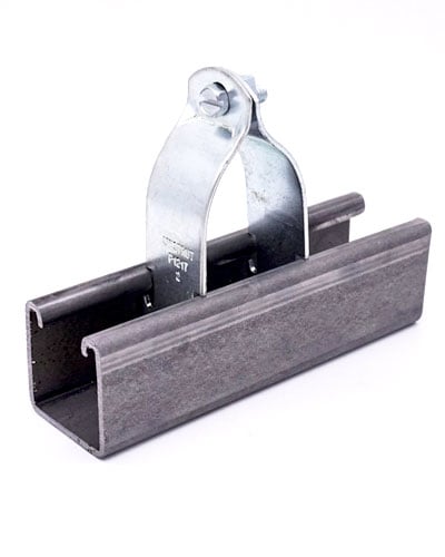


Unistrut P1835-EG - 3-Hole Trolley Clevis Fitting, Design Load 500 Lbs, Electro-Galvanized
Sku:
P1835-EG
UOM: EA

Sku:
P1835-EG
UOM: EA
Sliding Doors and Panels: Allowable load: 500 lbs. each*
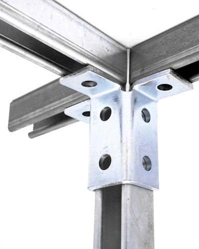
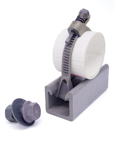
Doors and Panels can easily be hung from suspended strut using our P1835 clevis fittings. Our smooth-rolling wheels allow the door to easily glide along the track. Pair with our P1838 rubberized stops for a quiet stop at the end of the track.
Applications:
• Portable/moving walls (Pictured)
• Barn doors
• Sliding gates
* Based on allowable load for trolleys, actual allowable load may be determined by the allowable load of other strut/fittings.
Unistrut® is proud to have expanded the current trolley system to include 6 new trolley products! The newly expoanded Unistrut Trolley System now covers a much larger range of applications, allowing us to become your single source for both trolley and support systems.
P1835 – Clevis Fitting
P1836 – Trolley Tie
P1837 – Mid-Stop
P1838 – Quiet End Stop
P1839 – Cable Festoon
P1840 – Track Splice
FEATURES AND BENEFITS
Easy and customizable trolley systems
• Customize the optimal design for any application
• Application templates are available to make it quick and easy for the designer
• Connect the trolley system to any Unistrut system for additional customizability
High capacity and smooth operation
• The system can support heavy, medium, and light loads
• Smooth and reliable movements with self-cleaning bearings
• Quiet movement and stopping options available
Unistrut Buffalo is a division of Eberl Iron Works, Inc.
![]()
| SKU | P1835-EG |
|---|---|
| Pack Size | Each |
| UOM | EA |
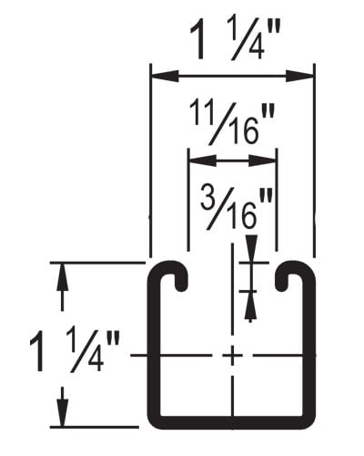
STANDARD DIMENSIONS
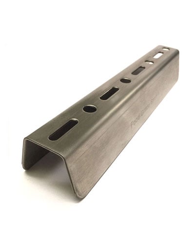
Standard Dimensions for 1-5/8" (41.3 mm) width series channel (Unless otherwise specified in Unistrut General Engineering Catalog):
Hole Diameter: 9/16" (14.3 mm)
Hole Spacing - From End: 13/16" (20.6 mm)
Hole Spacing - On Center: 1-7/8" (47.6 mm)
Width: 1-5/8" (41.3 mm)
Thickness: 1/4" (6.4 mm) with steel meeting or exceeding ASTM A1011 SS GR 33, or 0.220" (5.6mm) with steel meeting or exceeding ASTM A1011 HSLAS GR 45
Note: When used for mechanical supports, load capacities of brackets, fittings and other supporting elements should be in compliance with the American Standard Code for Pressure Piping. Clamps are designed to be used with W, M, S & HP Shape beams, Standard C & Misc. MC Channels, Angles & Structural Tees. Clamps must be used in pairs where indicated. For beam clamps with HG finish, standard hardware is EG finish. For optional stainless steel hardware, please contact the factory for availability.
MATERIAL
Fittings, unless noted, are made from hot-rolled, pickled and oiled steel plates, bar, strip or coil, and conform to one or more of the following specifications: ASTM specifications A575, A576, A635, A1011 SS GR 33, A1011 HSLAS GR 45 or A36. All fittings meet or exceed physical properties of ASTM A1011 GR 33. The pickling of the steel produces a smooth surface free from scale. Many fittings are also available in stainless steel, aluminum and fiberglass. Consult factory for ordering information.
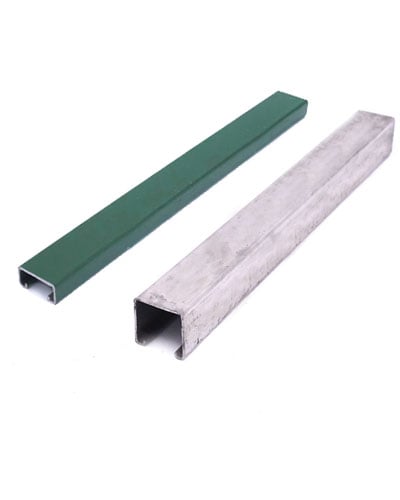
FINISHES
Fittings are available in:
*** Perma Green finish is a commercial grade finish, and as such scuffs and scratch marks are to be expected. If a flawless finish is desired, it is recommended to apply a matching touch up paint ***
APPLICATION
All parts drawings illustrate only one application of each fitting. In most cases many other applications are possible. The channels shown in the illustrations are P1000, 15⁄8" square, except where noted otherwise. All 9⁄16" diameter holes use 1⁄2" x 15⁄16" hex head cap screws and 1⁄2" nuts – P1010, P3010, P4010 or P5510 – depending on the channel used. Nuts and bolts are not included with the fitting and must be ordered separately.
DESIGN BOLT TORQUE
| Bolt Size | 1/4"-20 | 5/16"-18 | 3/8"-16 | 1/2"-13 | 5/8"-11 | 3/4"-10 |
|
Rec. Torque Ft/Lbs (N•m) |
6 (8) |
11 (15) |
19 (26) |
50 (68) |
100 (136) |
125 (170) |
|
Max Torque Ft/Lbs (N•m) |
7 (9) |
15 (20) |
25 (34) |
70 (95) |
125 (170) |
135 (183) |
SET SCREW TORQUE
| Bolt Size | 1/4"-20 | 5/16"-18 | 3/8"-16 | 1/2"-13 | 5/8"-11 | 3/4"-10 |
|
Set Screw Torque In/Lbs (N•m) |
6 (8) |
11 (15) |
19 (26) |
50 (68) |
100 (136) |
125 (170) |
DIMENSIONS
Imperial dimensions are illustrated in inches. Metric dimensions are shown in parenthesis or as noted. Unless noted, all metric dimensions are in millimeters and rounded to one decimal place.
DESIGN LOAD
Design load data, where shown, is based on the ultimate strength of the connection with a safety factor of 2.5, unless otherwise noted.
BEAM CLAMPS
Clamps are designed to be used with W, M, S and HP Shape beams, Standard C and Miscellaneous MC Channels, Angles and Structural Tees. Clamps must be used in pairs mounted in opposite directions where indicated. For beam clamps with HG finish, standard hardware is EG finish. For optional stainless steel hardware, please contact the factory for availability.
Save paper! Download the most up to date version of Unistrut's General Engineering Catalog, right here, in digital format.
*Please note, catalog is in PDF format. You must have Adobe Reader (a FREE and trusted program) installed, to view. If you do not already have Adobe Reader installed, you may download it from Adobe's website. *Download times may vary, file is large.*